
Elastomeric connectors provide a compact and reliable method for creating multiple electrical interconnections without soldering. Instead of permanent metal-to-metal joints, they establish electrical contact through controlled compression of conductive silicone structures.
This makes them especially suitable for LCD modules, displays, sensors, industrial devices, and other fine-pitch electronic assemblies where alignment tolerances, serviceability, and space constraints are critical.
Successful implementation depends less on the connector itself than on the overall system design. Mechanical compression, PCB pad geometry, and housing design all play a fundamental role in achieving reliable long-term electrical performance.
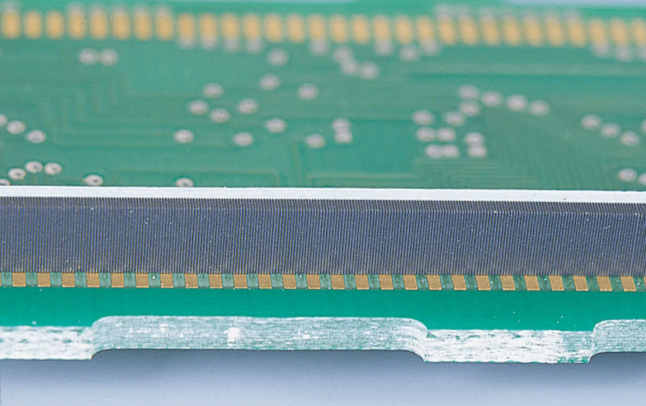
A ZEBRA® connector consists of alternating conductive and insulating silicone rubber layers laminated into a single elastomeric strip. When compressed between two contact arrays in a PCB-to-display or board-to-board interface, the conductive layers create vertical electrical paths while the insulating layers prevent current from flowing sideways.
This creates anisotropic conductivity, meaning electricity flows only through the thickness of the connector and not laterally between adjacent contacts. Each PCB pad typically overlaps several conductive layers simultaneously, creating multiple parallel contact paths.
This built-in redundancy improves tolerance to minor alignment errors, manufacturing variation, and surface imperfections while maintaining stable electrical performance. Unlike pin-based connectors, precise one-to-one alignment between individual conductive elements and PCB traces is unnecessary, provided sufficient overlap exists between the contact pads and conductive layers.
Electrical performance is determined by the complete interconnection system rather than by the connector alone. Contact resistance depends on the conductive material, compression level, PCB pad geometry, and the number of conductive layers engaged by each contact within the high-density interconnect. A well-designed interface ensures that each contact pad overlaps multiple conductive layers, providing redundant electrical paths and improving long-term reliability.
Compression is the single most important design parameter because an elastomeric connector functions as a compression connector, relying entirely on controlled mechanical force to establish electrical contact. Increasing compression enlarges the true contact area between the conductive layers and the PCB pads, reducing contact resistance and improving electrical stability. However, both insufficient and excessive compression can reduce reliability. Too little compression may lead to intermittent contact or open circuits, while excessive compression can permanently deform the silicone, introduce unnecessary stress into the PCB and housing, and shorten connector life.
Most ZEBRA® connectors are designed to operate within a compression range of approximately 5–25%, with 15–20% generally considered the optimum target for most applications. Compression should always be defined using the final assembled stack height, taking into account manufacturing tolerances of the PCB, housing, and connector itself.
To maintain consistent performance throughout the product's lifetime, the housing should incorporate a positive mechanical stop. This prevents over-compression while ensuring the connector remains within its intended operating range, even as the silicone naturally relaxes over time.
Because elastomeric connectors rely entirely on controlled compression, the surrounding mechanical structure is just as important as the connector itself. The housing must position the connector accurately, maintain consistent compression throughout the product's lifetime, and allow the silicone to deform in a controlled manner.
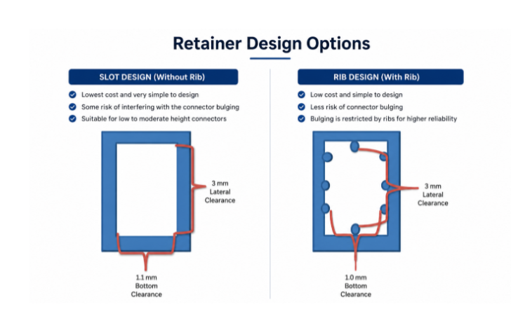
Two common retainer designs are used: slot designs and rib designs.
A slot design uses a simple rectangular cavity to locate the connector. It is the simplest and most economical solution to manufacture and works well for low- to moderate-height connectors. However, because the connector is only constrained by the cavity walls, it has greater freedom to bulge laterally as it is compressed. If insufficient clearance is provided, this expansion can increase internal stress and affect contact consistency.
A rib design incorporates small ribs or support features within the cavity to control how the connector expands during compression. By limiting excessive bulging and helping maintain a more uniform contact pressure, rib designs generally provide improved mechanical stability and are often preferred for taller connectors or applications where maximum long-term reliability is required.
Regardless of the retainer style, the connector should never be completely constrained. Small clearances around the sides and bottom of the connector are required to accommodate the natural deformation of the silicone during compression. The recommended clearance depends on connector dimensions, compression level, and assembly tolerances, but should always allow controlled expansion without permitting excessive movement.
As connector height increases, retainer design becomes progressively more important for maintaining uniform compression across the entire contact area and ensuring consistent electrical performance.
Printed circuit board (PCB) pad geometry has a significant influence on electrical reliability. Each contact pad should be sufficiently wide to overlap several conductive layers, providing multiple electrical contact paths for fine-pitch PCB layouts. This redundancy allows the connector to compensate for manufacturing tolerances while maintaining stable electrical contact.
Pads that are too narrow reduce the number of available conductive paths and increase the likelihood of intermittent connections. Similarly, adequate spacing between adjacent pads is required to prevent electrical bridging under normal manufacturing tolerances.
Because elastomeric connectors are manufactured from hundreds of laminated conductive and insulating layers, small variations in conductor pitch and slight skew of the conductive elements are inherent to the manufacturing process. PCB pad dimensions and spacing should therefore accommodate these normal manufacturing tolerances to maintain reliable electrical isolation. Reducing pad spacing excessively can increase the risk of unintended bridging without providing meaningful improvements in electrical performance.
The electrical performance of an elastomeric connector is determined by both its conductive structure and the mechanical design of the assembly. Contact resistance, current-carrying capability, and signal integrity are influenced by the conductive material, compression level, PCB pad geometry, and the number of conductive paths engaged by each contact.
Stable electrical performance depends on maintaining consistent compression, adequate contact area, and sufficient redundancy between the PCB pads and the conductive elements of the connector. Proper mechanical design is therefore just as important as the connector itself in achieving reliable long-term operation.
Different ZEBRA® connector constructions are available to meet varying electrical performance requirements, ranging from economical low-current solutions to high-performance designs with exceptionally low contact resistance.
Consistent electrical performance also depends on allowing for normal manufacturing tolerances, including minor variations in conductor pitch and skew, through appropriate PCB pad design and spacing.
One of the major advantages of elastomeric connectors is their ability to maintain reliable electrical contact in mechanically demanding environments. Their compliant structure provides excellent resistance to vibration and repeated mechanical loading while avoiding the fretting wear commonly associated with rigid metal contacts.
Like all silicone components, elastomeric connectors experience some compression set over time. For this reason, long-term reliability depends on maintaining controlled compression through proper housing design rather than relying solely on the elasticity of the material. Clean contact surfaces and stable mechanical alignment are equally important for achieving consistent performance throughout the product's service life.
Most problems encountered with elastomeric connectors originate from mechanical design rather than electrical limitations.
Typical causes include:
These issues can generally be eliminated through appropriate housing design, correct compression control, and proper PCB layout.
Carbon ZEBRA® Connectors
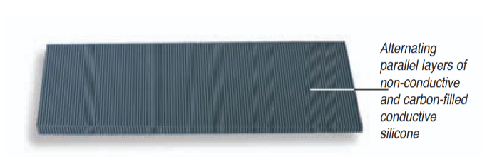
Carbon ZEBRA® connectors are the most economical option and are widely used in low-current applications such as segmented LCD displays. Their carbon-filled conductive silicone provides reliable electrical contact where current requirements are minimal, making them an excellent choice for cost-sensitive designs.
Silver ZEBRA® Connectors
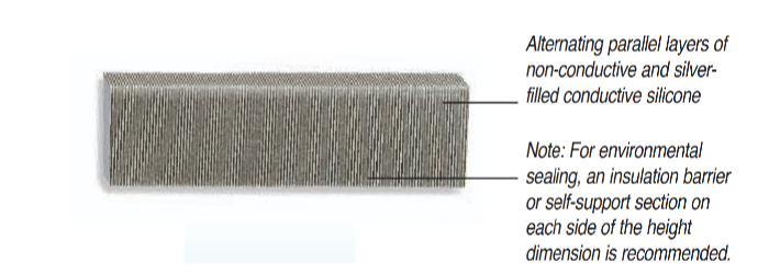
Silver ZEBRA® connectors replace the carbon-filled conductive layers with silver- filled silicone, significantly reducing contact resistance while maintaining the same mechanical construction. They are well suited to applications requiring improved signal integrity, lower voltage drop, or enhanced electrical performance without major changes to the mechanical design.
ZEBRA® GOLD 8000 Connectors
ZEBRA® GOLD 8000 Connectors use thousands of extremely fine gold-plated nickel wires embedded within silicone rubber rather than conductive silicone layers. This construction provides exceptionally low contact resistance, excellent signal transmission, and substantially higher current-carrying capability than conventional conductive silicone connectors.
Although the internal construction differs, the operating principle remains the same. Reliable performance still depends on controlled compression, appropriate PCB pad geometry, and a properly designed housing with adequate mechanical support.
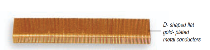
In general, carbon connectors provide the most economical solution for low-current applications, silver connectors offer improved electrical performance for a wide range of electronic systems, while ZEBRA® GOLD 8000 Connectors are preferred wherever the lowest possible contact resistance and highest current capability are required.
Elastomeric connectors provide a compact and reliable method of creating high-density electrical interconnections without soldering. While the choice between Carbon ZEBRA®, Silver ZEBRA®, and ZEBRA® GOLD 8000 Connectors depends on the required electrical performance, successful implementation ultimately relies on sound mechanical design.
Careful attention to compression control, PCB pad geometry, housing design, and connector selection enables engineers to achieve robust, vibration-resistant interconnections with excellent long-term reliability across a wide range of electronic applications.
Our engineering team can help you find the right Fujipoly solution for your specific application. Get in touch to discuss your requirements or request a sample.
Request a Sample