Carbon Connector
These connectors provide reliable connections by being compressed between contact surfaces and are commonly used to connect LCDs, from small watch displays to large instrument panels.

Product Overview
FUJIPOLY connectors (see figure 1) have alternating layers ZEBRA® of conductive carbon-filled and non-conductive silicone rubber. Table A shows the different types of ZEBRA® connectors available. Table C shows performance characteristics. Figure 1 shows the three dimensions of the ZEBRA® connector. When ordering, the three dimensions should be specified within the limits shown in table B. For best overall performance, ZEBRA® connectors must be ordered and used with a ratio of H/W equal to or greater than 1.5.
Table A
(CZ410/CZ710)
0.10 mm
0.15 mm
0.025 mm
0.10 mm
230 mm
0.50 mm
0.18mm
0.25 mm
0.050 mm
0.15 mm
230 mm
(CZ405/CZ705)
0.25 mm
0.050 mm
0.10 mm
0.010 mm
0.060 mm
230 mm
Table B
2.410 in. to 6.00 in. — ± 0.015 in. ……………./……………. 61.2 mm to 152.4 mm — ± 0.38 mm
6.010 in. to 7.87 in. — ± 0.020 in. ……………./……………. 152.6 mm to 200.0 mm — ± 0.50 mm
0.040 in. to 0.079 in. — ± 0.003 in………………/…………….. 1.01 mm to 2.0 mm — ± 0.076 mm
0.080 in. to 0.118 in. — ± 0.005 in………………/…………….. 2.01 mm to 3.0 mm — ± 0.127 mm
above 0.118 in./3.00 mm consult factory.
Table C
-40°C
100°C
ZEBRA® Connector Dimensions
Figure 2 shows the three dimensions of the ZEBRA® connector. When ordering, the three dimensions should be specified within the limits shown in Table B. For best overall performance, ZEBRA® connectors must be ordered and used with a ratio of H/W equal to or greater than 1.5. Details show silicone support (left) and insulation barrier (right). Each is available on one or both sides. Configurations may also include support on one side and insulation on the other.
ZEBRA® CONNECTOR INSULATING BARRIER
(B) mm
0.050 ± 0.025
Nominal Resistance Calculation
To calculate the resistance of the ZEBRA® connector use the following formulas:
Where:
Cw = Contact pad width in inches
H = ZEBRA® connector height in inches
W = ZEBRA® connector width in inches
Metric:
Inches:
Where:
R = Resistance (Ω)
Ew = Electrode Pad width (mm or inches)
W = Connector width (mm or inches)
H = Connector height (mm or inches)
Nominal Force Deflection Plain ZEBRA or Insulation Barrier Type
ZEBRA® connectors should be deflected 5% to 25% of H. To calculate F-Force for deflection, use the following formula: F = Force (N)
H = Height of connector (mm or inches)
H1 = Deflected height of connector (mm or inches)
W = Width of connector (mm or inches)
W1 = Width of ZEBRA portion (mm or inches)
L = Length of connector (mm or inches)
Metric: F(N) = 9 x D x W x L x 9.8 x 10⁻³
Inches: F(N) = 5806 x D x W x L x 9.8 x 10⁻³
Metric:
F(N) = [(9 x D x W1 xL) + {2.2 x D x (W-W1) x L}] x 9.8 x 10⁻³
Inches:
F(N) = [(5806 x D x W1 x L) + {1419 x D x (W-W1) x L}] x 9.8 x 10⁻³
Part Number and Nomenclature:
To specify a connector to your exact requirements, substitute the metric measurements for width, length and height according to instructions below; example part# Ag(2.0 IB1 x 20 x 2.0)-U;
Rich experience in diverse industries
Regulatory Information
Our company has earned various certificates in the thermal interface material field. Some certifications show parent & sister companies, not FUJIPOLY Europe B.V.


IATF 16949:2016
Ensures automotive-grade quality and reliability, meeting global industry standards.

ISO 9001:2015
Guarantees a strong quality management system for consistent excellence and customer satisfaction.
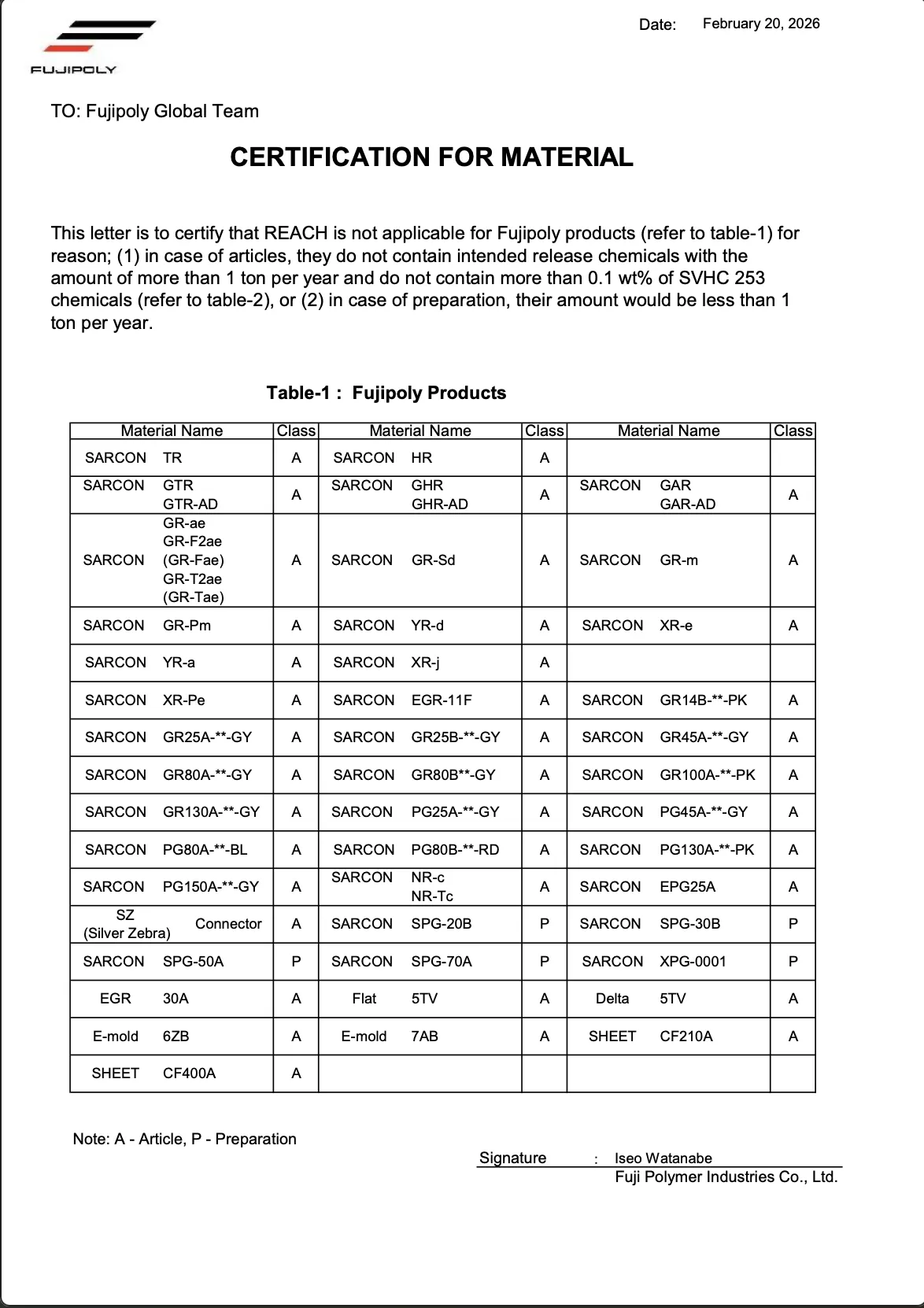

REACH
Confirms compliance with EU safety standards, ensuring environmentally safe materials.
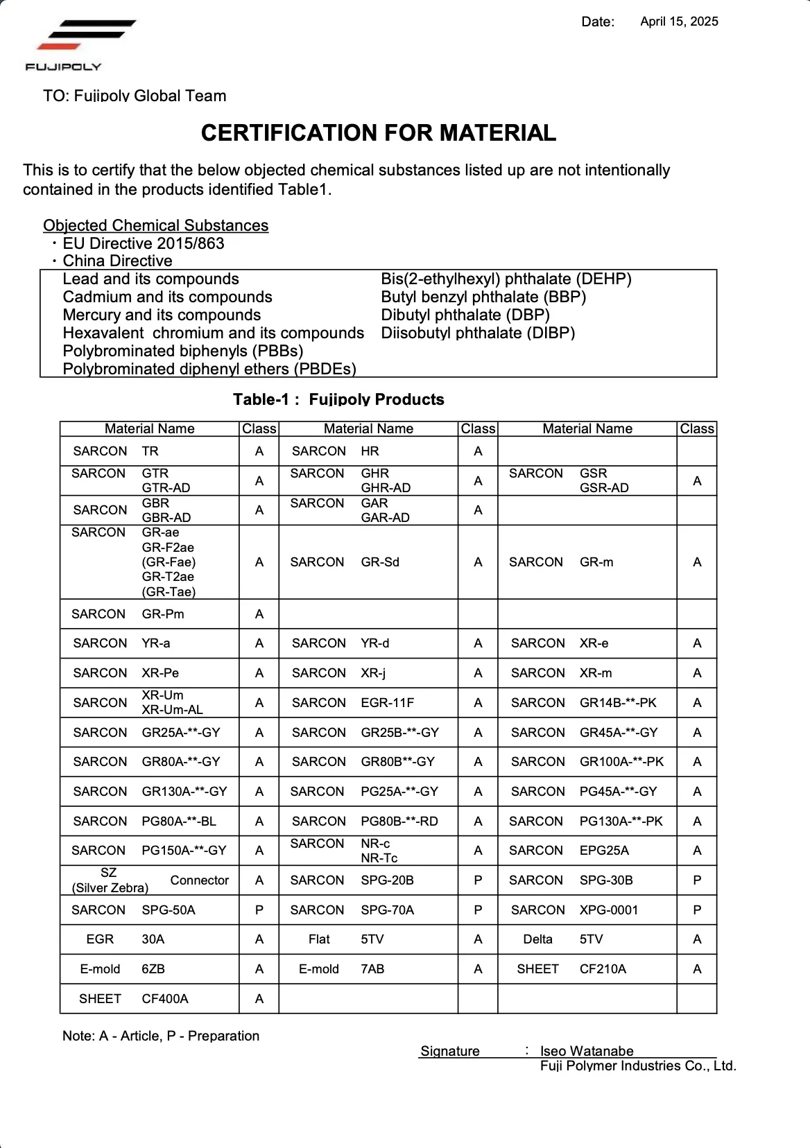

RoHS
Demonstrates a commitment to eco-friendly products free from hazardous substances.

Conflict Mineral Reporting (Contains Cobalt)
Conflict Mineral Reporting (Contains Mica)
Conflict Mineral Reporting
Supports ethical sourcing and responsible supply chains.
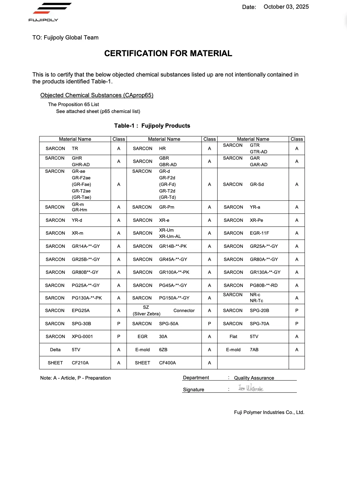

Prop 65
Ensures products meet California's strict health and safety regulations.


Halogen Free Statement
Reflects a commitment to safer, environmentally friendly, and non-toxic materials.

Our Process
01
Consultation and Coordination
The Customer would put a simple inquiry. A technical Support Engineer would go through the inquiry and generate the necessary drawings through specific dimensions. This would lead to a quote being sent out to the customer for final approval from both B2B parties.
02
Making Sample Request
If approved, the customer would be able to request a sample of the material that they have requested from the initial Consultation and Coordination.
03
Order Confirmation
If approval has been completed, an official order would be sent across to Fujipoly Europe B.V. that the Customer Service Department would prioritise to make sure that the order would be completed on time.
Frequently asked questions
Information about how ZEBRA Connectors work, the benefits, application methods, or safety considerations.
The volume of the slot should be equal to or slightly greater than the volume of the connector. Consider all tolerances when determining the max volume of the connector. E.g.; Connector H x W x L= Volume
Fujipoly’s UL file number is E58126.
A minimum aspect ratio of 1.5 to 1 is recommended. The aspect ration only applies to the Zebra itself and not the optional support material.
Compression set for a plain Zebra (Silver, Carbon, or Low-Temp) is 10% to 15% of the compressed amount. Compression set for a supported Zebra is 30% to 40% of the compressed amount.

