Gold 8000 Connectors
The FUJIPOLY ZEBRA Series 8000 elastomeric connector elements are D-shaped, low durometer silicone elastomer cores around which flat metallic gold-plated conductors are vulcanized in a row parallel to each other.

Product Overview
The point contact will penetrate surface oxides or contaminants which might be present on the surface of the contact pads, thus assuring reliable electrical connection on two planes. Also available are standard board to board assemblies which include connector and holder.
Dimensional Specifications
Materials
Performance Characteristics
Regulatory Information
Our company has earned various certificates in the thermal interface material field. Some certifications show parent & sister companies, not FUJIPOLY Europe B.V.


IATF 16949:2016
Ensures automotive-grade quality and reliability, meeting global industry standards.
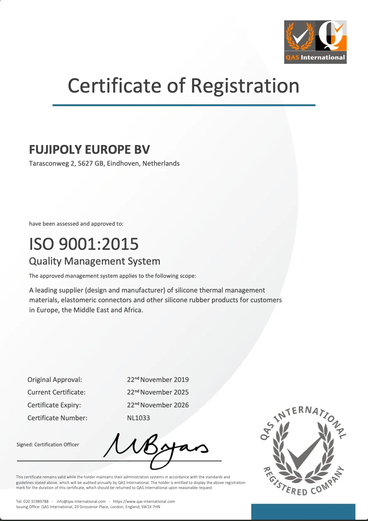

ISO 9001:2015
Guarantees a strong quality management system for consistent excellence and customer satisfaction.
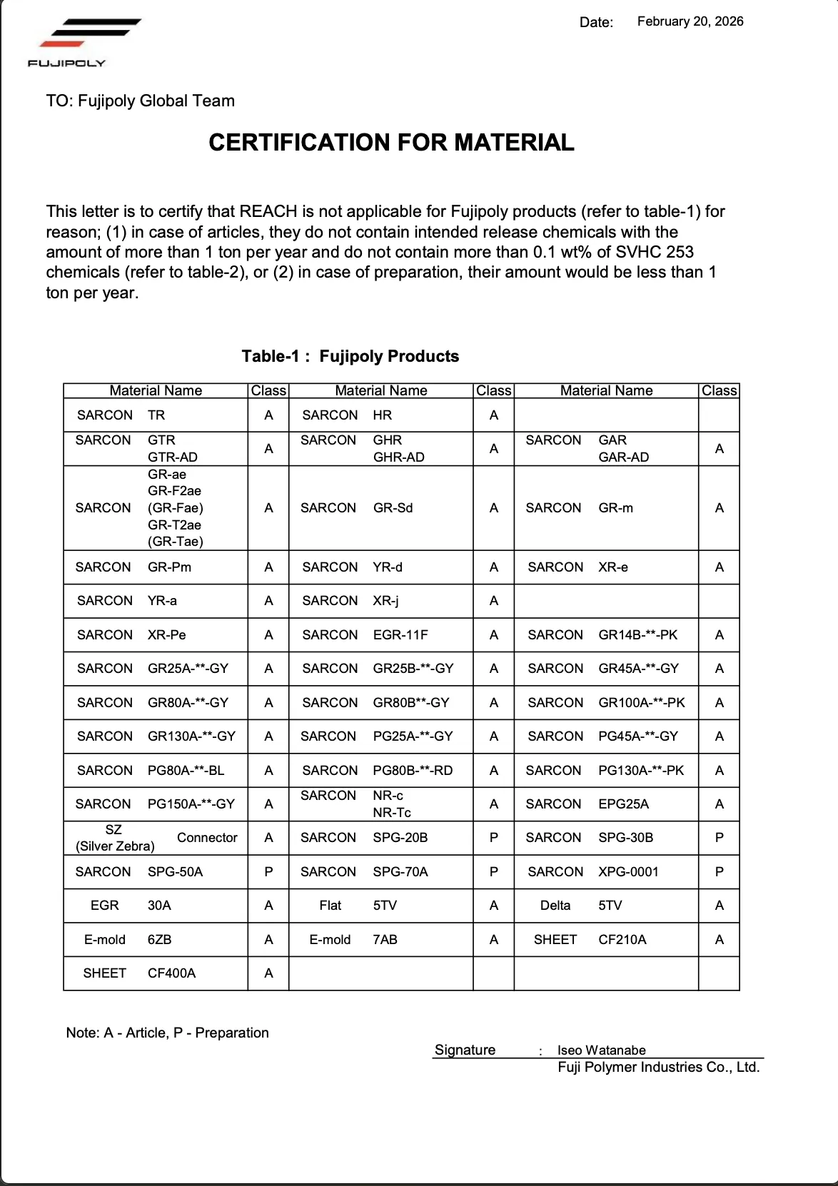

REACH
Confirms compliance with EU safety standards, ensuring environmentally safe materials.
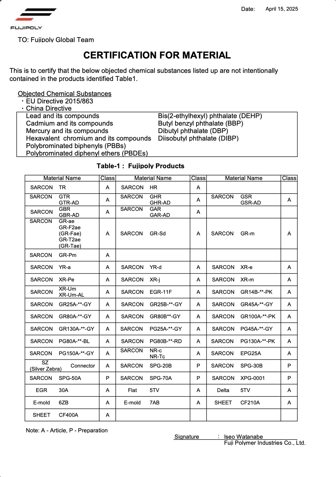

RoHS
Demonstrates a commitment to eco-friendly products free from hazardous substances.

Conflict Mineral Reporting (Contains Cobalt)
Conflict Mineral Reporting (Contains Mica)
Conflict Mineral Reporting
Supports ethical sourcing and responsible supply chains.
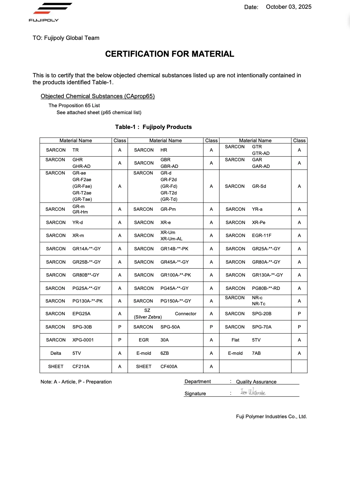

Prop 65
Ensures products meet California's strict health and safety regulations.


Halogen Free Statement
Reflects a commitment to safer, environmentally friendly, and non-toxic materials.

Our Process
01
Consultation and Coordination
The Customer would put a simple inquiry. A technical Support Engineer would go through the inquiry and generate the necessary drawings through specific dimensions. This would lead to a quote being sent out to the customer for final approval from both B2B parties.
02
Making Sample Request
If approved, the customer would be able to request a sample of the material that they have requested from the initial Consultation and Coordination.
03
Order Confirmation
If approval has been completed, an official order would be sent across to Fujipoly Europe B.V. that the Customer Service Department would prioritise to make sure that the order would be completed on time.
Frequently asked questions
Information about how ZEBRA Connectors work, the benefits, application methods, or safety considerations.
The volume of the slot should be equal to or slightly greater than the volume of the connector. Consider all tolerances when determining the max volume of the connector. E.g.; Connector H x W x L= Volume
Fujipoly’s UL file number is E58126.
A minimum aspect ratio of 1.5 to 1 is recommended. The aspect ration only applies to the Zebra itself and not the optional support material.
Compression set for a plain Zebra (Silver, Carbon, or Low-Temp) is 10% to 15% of the compressed amount. Compression set for a supported Zebra is 30% to 40% of the compressed amount.

