Zebra® Gold 8000
The FUJIPOLY ZEBRA® Series 8000 elastomeric connector elements are D-shaped, low durometer silicone elastomer cores around which flat metallic gold-plated conductors are vulcanized in a row parallel to each other. The tips of the metallic conductors are turned upward so that point contact can be effected; in addition, contact is made to the flat area when the connector element is positioned between two printed circuit boards. The point contact will penetrate surface oxides or contaminants which might be present on the surface of the contact pads, thus assuring reliable electrical connection on two planes. Also available are standard board to board assemblies which include connector and holder.
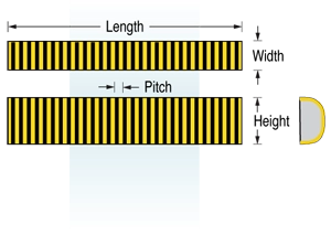
Dimensional Specifications
| Connector Dimensions* | Minimum | Maximum |
|---|---|---|
| Length = L | 0.200” ± 0.005” 5.08mm ± 0.127mm | 6.000” ± 0.030” 152.4mm ± 0.762mm |
| Height = H | 0.100” ± 0.005” 2.54mm ± 0.127mm | 0.500” ± 0.015” 12.70mm ± 0.381mm |
| Width = W | 0.060” ± 0.005” 1.52mm ± 0.127mm | 0.125” ± 0.010” 3.18mm ± 0.254mm |
Note: For good design practice and low deflection force requirements, the height “H” should be twice the width “W”. For other sizes consult factory.
Materials
| Connector Component | Materials Used |
|---|---|
| Conductive Elements | Gold-plated copper wire. gold 0.00025mm (0.00001”), nickel 0.0013mm (0.00005”). |
| Wire Size and Spacing (Series 8000 A,B and C) |
A. 0.05mm x 0.127mm (0.002” x 0.005”) flat wire on 0.25mm (0.010”) center-to-center spacing. (Min. 100 wires/ inch.) B. 0.05mm x 0.10mm (0.002” x 0.004”) flat wire on 0.19mm (0.0075”) center-to-center spacing. (Min. 133 wires/inch.) C. 0.025mm x 0.076mm (0.001” x 0.003”) flat wire on 0.15mm (0.006”) center-to-center spacing. (Min. 166 wires/inch.) |
| Connector body | Non-conductive tan color silicone rubber. UL-94-HB rating, 500 volts/mil dielectric strength. |
| Film | 0.025mm (0.001”) thick polyamide dielectric strength of film ASTM-D-149, 2000 volts/mil. |
Performance Characteristics
| Parameter | Conditions and Performance |
| Contact Resistance | Less tdan 25 milliohms on 0.025” wide contact pads; 0.100 amperes DC, Kelvin- type four probe test metdod |
| Insulation Resistance | Minimum 1012 ohms between adjacent conductive elements. |
| Current Carrying Capacity | Series 8000 A and B, 500 mA per wire max.; Series 8000 C, 250 mA per wire max. |
| Capacitance | Maximum 0.100 picofarads per adjacent pad at 1 MHz and 0.100” high (“H”). |
| Inductance | Maximum 7 nanohenries per adjacent pad at 1 MHz and 0.100” high (“H”). |
| Repeated Actuations | 500 actuations witdout appreciable change in contact resistance (deflection of 15%). |
| Deflection | 8% to 20%. Recommended deflection 10 to 15% of original height. |
| Deflection Force/Inch | 4lbs. per linear inch for 15% deflection for a 0.062” (“W”) x 0.285 (“H”) connector. |
| Operating Temperature Range | -20° C min., 125° C max. |
| Salt Spray Test | MIL-STD-202E, metdod 101D, condition B. 5% salt solution 95° F, 48 hours. tdere was no evidence of blistering or peeling of tde contact material. |
| Temperature Cycling | MIL-STD-202E, metdod 102A, condition D, -55° C, 25° C, 125° C. tdere was no change in tde physical properties of tde specimens. |
| Humidity (Steady State) | MIL-STD-202E, metdod 103B, condition C modified. 95% RH room temperature. tdere was no appreciable change in contact resistance after 500 hours exposure. |
| Corrosive Environment | 1,000 hours exposure at 1 ppm H2S and 1 ppm O2, 60° C AND 75% RH. Slight change in contact resistance; no evidence of contact peeling or blistering. |