Elastomeric Connectors
• High Density, increased number of I/O’s
• Low resistance, high current capacity
• Low insertion force, low compression force
• Redundant contact engagement
• High electrical and mechanical reliability
• Chemical stability, degradation resistance
• Cost-effectiveness, ease of assembly
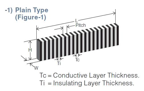
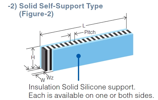
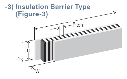
ZEBRA Elastomeric Connectors are constructed of alternating parallel layers of electrically conductive and non-conductive silicone elastomer.ZEBRA provides a redundant connection with a minimum of two conductive layers recommended per PC contact pad. The connector is available with insulating barrier or silicone supports
| Zebra® Carbon Connectors | Economical general use with contact pitches at 140, 240 or 500 per inch |
| Zebra® Silver Connectors | 300mA current carrying capacity, rugged long-life aging with contact pitches at 240 per inch |
| Zebra® Gold 8000 Connectors | Zero insertion force, tight pitch, low compression force, very low resistance, very high current carrying capacity |
| W-Series Matrix Connectors | A range of 300 to 2,000 fine metal wires per 1 cm2 embedded in the rubber sheet |
| CZ405/CZ705/2005 | CZ410/CZ710/1002 | CZ418/2004 | CZ610/LT200 | SZ100/5002 | ||
| Metal Particles for Conductive Layers | Carbon | Carbon | Carbon | Carbon | Silver | |
| Contact Area Pitch: Contact Spacing Center-to-Center | Minimum | 0.25mm 0.010in. |
0.38mm 0.015in. |
0.50mm 0.020in. |
0.38mm 0.015in. |
0.38mm 0.015in. |
| Pitch (Ti+Tc): Sum of the Thickness of an Adjacent Conductive and Non-conductive Layer |
Normal | 0.050mm 0.002in. |
0.10mm 0.004in. |
0.18mm 0.007in. |
0.10mm 0.004in. |
0.10mm 0.004in. |
| Maximum | 0.10mm 0.004in. |
0.15mm 0.006in. |
0.25mm 0.010in. |
0.15mm 0.006in. |
0.152mm 0.006in. |
|
| Conductive Layers | Minimum | 160/10mm 500/in. |
88/10mm 240/in. |
45/10mm 140/in. |
88/10mm 240/in. |
66/10mm 240/in. |
| Individual Conductive and Insulating Layer Thickness |
Minimum | 0.010mm 0.0004in. |
0.025mm 0.001in. |
0.050mm 0.002in. | 0.025mm 0.001in. | 0.025mm 0.001in. |
| Contact Area Pitch: Contact Spacing Center-to-Center |
Maximum | 0.060mm 0.0024in. |
0.10mm 0.004in. |
0.15mm 0.006in. |
0.10mm 0.004in. |
0.075mm 0.003in. |
| Available Lengths | Maximum | 230mm 9.0in. |
230mm 9.0in. |
230mm 9.0in. |
127mm 5.0in. |
127mm 5.0in. |
| Length (L) | 4.0 to 61.0mm : ±0.20mm | 0.157 to 2.40in. : ±0.008in. | 6.35±0.12 to 127.0±0.64mm |
|||
| 61.2 to 152.4mm : ±0.38mm. | 2.41 to 6.00in. : ±0.0.015in | |||||
| 152.6 to 200.0mm : ±0.50mm. | 6.01 to 7.87in. : ±0.02in | 0.25±0.005 to 5.0±0.025in. |
||||
| 200.1 to 230.0mm : ±1.00mm . | 7.88 to 9.00in. : ±0.039in | |||||
| Height (H) | 0.5 to 19.0mm : ±0.127mm | 0.02 to 0.75in. : ±0.005in. | 1.0±0.08 to 12.7±0.18mm |
|||
| above 19.0mm / 0.75in. Consult factory | 0.04±0.003 to 0.5±0.07in. |
|||||
| Width (W) | 0.38 to 1.0mm : ±0.05mm . |
0.015 to 0.039in. : ±0.002in. | 0.5±0.08 t 2.54±0.13mm 0.02±0.003 to 0.1±0.005in. |
|||
| 1.01 to 2.0mm : ±0.076mm | 0.040 to 0.079in. : ±0.003in | |||||
| 2.01 to 3.0mm : ±0.127mm | 0.080 to 0.118in. : ±0.005in. | |||||
| above 3.0mm / 0.118in. Consult factory | ||||||
| Temperature Range | -40 to +100°C -40 to +212°F |
-65 to +125°C -85 to +260°F |
-40 to +185°C -45 to +80°F |
|||
| Current Carrying Capacity | 2 0.005A/0.04”x0.04” pad |
2 0.3A/0.04”x0.04” pad |
||||
| Resistance Between Layers | 1012ohms | |||||
RESISTANCE –
To calculate the resistance of ZEBRA connectors, choose one of the following formulas:
| For Carbon ZEBRA | For Silver ZEBRA | Where: | W = Width of ZEBRA® Ew = Electrode pad width H = Height of ZEBRA® |
|||||||||||||
| Metric: | R = | 60 x H | Inches: | R = | 2.37 x H | Metric: | R= | H x 0.01 | +0.1 | Inches: | R = | H x 0.0004 | +0.1 | |||
| Ew x W | Ew x W | W x Ew | W x Ew | |||||||||||||
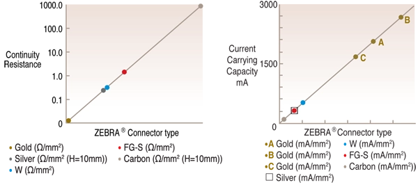
Typical Performance Characteristics:
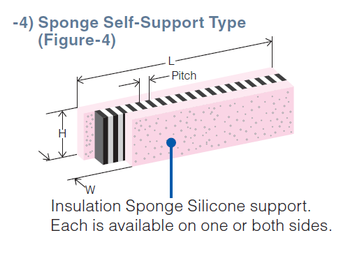
Side Support or Insulation Barrier:
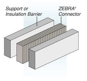
Drawing on the left shows side support or insulation on one or both sides, or one of each. Various materials are available from the minimum insulating barrier of 0.05mm to support layers of up to 1.5mm. Support layers can be soft silicone rubber, or medium and soft silicone sponge. Recommended height is twice the width for minimum force deflection.
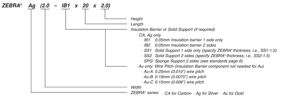
Part Number and Nomenclature:
To specify a connector to your exact requirements, substitute the metric measurements for width, length and height according to instructions below; example part# Ag(2.0 IB1 x 20 x 2.0)-U;