Zebra® Silver Connectors
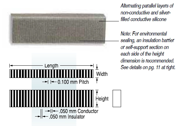
FUJIPOLY low resistance ZEBRA® elastomeric connectors are constructed of alternating parallel layers of electrically conductive and non-conductive silicone elastomer. The electrically conductive layer is filled with silver-metal particles.
The composite alternating layers provide reliable electrical connection when placed between two aligned conducting surfaces.
The low resistance ZEBRA® provides a redundant connection with a minimum of two conductive layers recommended per PC contact pad. The connector is available with insulating barrier or silicone supports (See page 6). The connectors are used for connecting electroluminescent (EL) and plasma type displays to PC boards or for connecting hybrid circuits to PC boards, among other applications.
Low resistance ZEBRA® connectors are positioned between two aligned surfaces and are mechanically clamped together with a lid or another PC board. The connectors may be free standing or positioned in a retainer depending on packaging profiles and design.
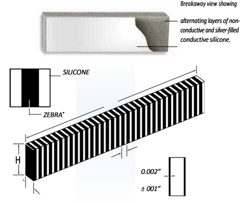
Self Support And Insulation Barrier
Breakaway view showing alternating layers of non- conductive and silver-filled conductive silicone.
DESIGN RECOMMENDATIONS
Recommended deflection range is 5-25% of free height. Minimum deflection will vary with packaging applications and should consider overall height, PC board warpage, finish, etc. (Contact Fujipoly Product Application Engineering for assistance.) Design recommendations for solid ZEBRA® over 0.400” deflect 0.050” maximum. Silicone supported over 0.400” deflect 0.060” typical.
| Item | Standard | Test Method |
| High Temperature | MIL-202D-108A | 85° C 1500 hr |
| Low Temperature | – | -40° C 500 hr |
| Moisture | MIL-202D-103B | 40° C 95% RH x 500 hr (250mA/pad) |
| Thermal Cycle | MIL-202E-107G | 65°C/25°C/150°C/ 25°C, 5 cycles |
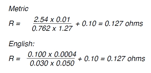
Nominal Resistance Calculation
For the purpose of calculating the resistance of silver ZEBRA® connectors and testing them for compliance please use the following formula:
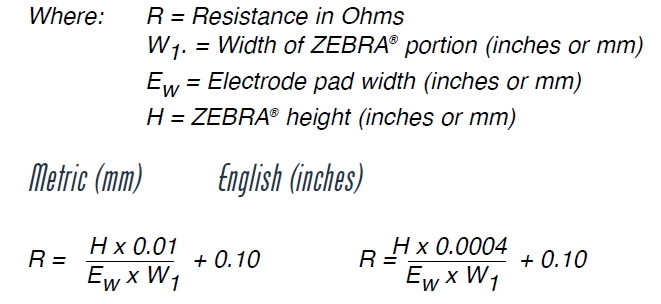
Example: if ZEBRA® is 0.100”/2.54 mm H and 0.030”/0.762mm W, then the maximum resistance on a 0.050”/1.27 mm wide pad will be: